How To: Automate an SMS Response to a Customer Call
This topic presents a very simple example of the Genesys “Omnichannel” capability, coordinating different media channels when a customer reaches out to your contact center. It will illustrate how you might automatically generate and send an SMS to a customer who had just made a voice call to your contact center, perhaps offering the caller a link to a survey or confirmation of the case number.
This example also shows how interactions from distinct media can be linked in a step-by-step workflow created in Composer, the Genesys tool that allows you to model your business. Composer-created workflows are executed by Orchestration Server, the Genesys engine that allows different media (voice, email, chat, SMS, and so on) to be coordinated and thereby enhance the customer experience. While the example here demonstrates a voice call synching with an SMS, you can also use Composer for many other types of Omnichannel routing.
The Building Blocks
This workflow diagram below was built with the following Composer blocks:
- Entry and Exit blocks
- Play Application block
- Target block
- SCXML State block
- Create SMS block
- Send SMS block
The Workflow Diagram
This is the finished workflow diagram that we will explore. The configuration for each block is shown further ahead. To start a diagram in Composer, select New > Java Composer Project, enter a name, select Integrated Voice and Route (in this case), then click Finish.
The diagram creation process goes like this: You drag and drop blocks from Composer's palette of blocks, configure the block properties, connect the blocks, Save, Validate, and Generate the code (SCXML).
For more detail, see Creating a New Routing Project.
Configuring the Entry Block
Note the Entry block at the top of the above diagram and the Exit block at the bottom. Every diagram starts with an Entry block and ends with an Exit block.
Workflow diagram-building blocks are contained in Composer's palette of blocks, which appears on the side of the Composer UI.
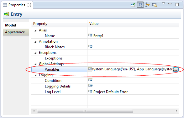
Each block has configurable properties (fields) associated with it. Dragging and dropping a block from the palette into the design area automatically opens a view for that block where you configure properties associated with the block. The Properties view shown opposite is for the Entry block. Selecting a block already placed in the design area also opens the Properties view for that block.
Configuring Entry Block Variables
One function of the Entry block is to define variables. You open the dialog box shown on the left for defining variables by clicking the button opposite Variables (see Properties view above). You have the option of assigning values to predefined System and Application variables. Or you can define your own User variables.
The Variables dialog box in this example shows two user-defined variables defined: SMS_Text and PhoneNumber.
Configuring the Play Application Block
The second block in the diagram is a Play Application block. This block executes an application or a script on a device, such as an Interactive Voice Response unit (IVR).
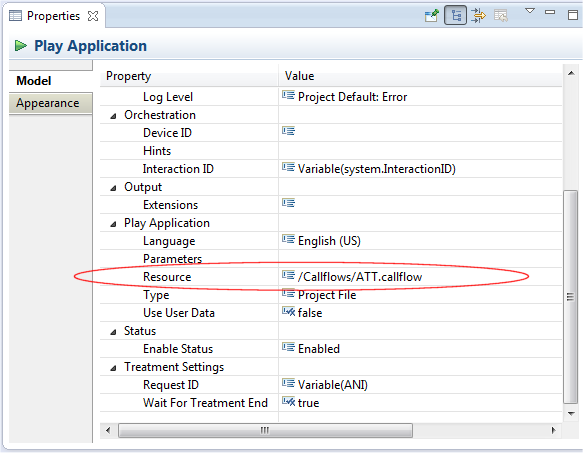
In the example diagram, the Play Application block plays a voice recording to the calling customer. As shown by the Resource property, the Play Application block plays the recording associated with the ATT.callflow. This callflow would be part of the same Project file containing the workflow diagram being described here.
Configuring the Target Block
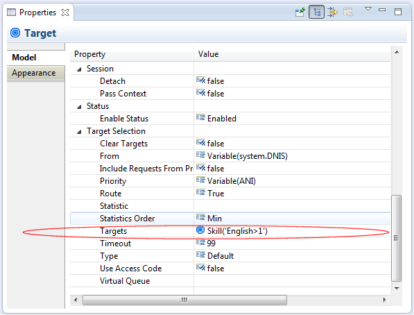
The third block in the diagram is a Target block. This block routes a customer interaction to to an agent based on the Target Type criteria you select. The Target block in our example diagram routes based on agent Skill. The skill expression shown for the Targets property instructs to route the interaction to an agent having an English Skill greater than "1".
Configuring the SCXML State Block
The fourth block in the diagram is a SCXML State block. This block gives the option of including custom code in the SCXML document that Composer generates based on the workflow diagram.
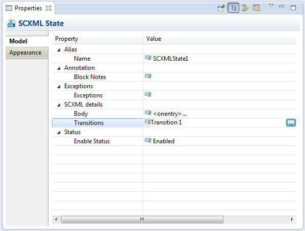
The SCXML State block in our example diagram contains Transitions 1 (a user-defined name) for the Transitions Property used for transitioning from voice to SMS. Clicking the button opposite the Transitions property shows Transition 1 defined as interaction.deleted.
[+] Background on SCXMLNote: The SCXMLState block has a Target previously defined for Transition 1 so it does not need the Body property. Although not shown here, there could be an outport on the SCXML State block connected to another block that could provide logic to be executed when interaction.deleted is received.
Configuring the Create SMS Block
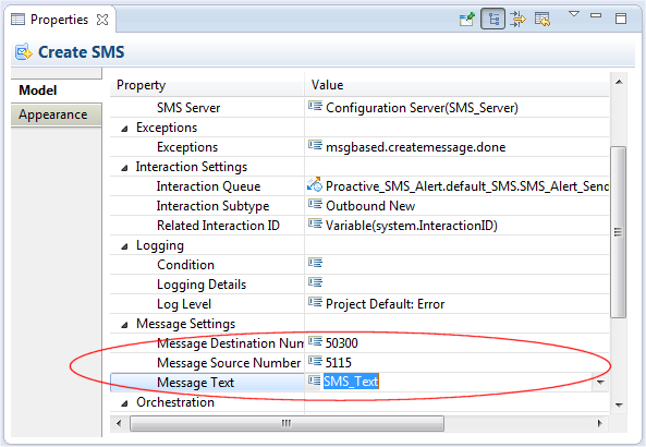
The fifth block in the diagram is a Create SMS block used to create an outbound message, which can be sent out as a Short Message Service (SMS) text to an external SMS Server. SMS refers to the common text messaging service available on cellphones and other handheld devices.
Block properties include the Message Text, Outbound Queue for the outbound message, the Message Destination Number, and the Message Source Number.
The Message Text can be manually entered or be contained in variable. The example diagram uses the SMS_Text variable previously defined in the Entry block.
Configuring the Send SMS Block
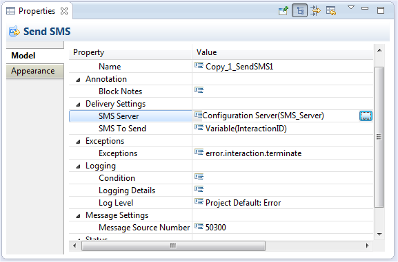
The sixth block in the diagram is a Send SMS block. This block sends the SMS message created with the Create SMS block to the SMS server.
Why Would I Use This?
There are number of reasons why you might want to configure this type of workflow where a calling customer is sent a text message. A few examples are presented below.
[+] Last Call Agent Unavilable


