Routing Principles in SIP Cluster
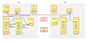
The following sample deployment diagram illustrates the routing principles in SIP Cluster:
In the above diagram, there are two data centers (DC1 and DC2) with two SIP Cluster nodes in each data center. All SIP Cluster nodes share the same SIP Cluster Switch where all Routing Point DNs and agent DNs are configured. Each SIP Cluster node has a dedicated routing solution consisting of URS, ORS, and Stat Server. A call distributed to a SIP Cluster node is handled by the routing solution of this node, by executing a strategy assigned to a Routing Point.
To simplify provisioning and improve performance, the SIP Cluster architecture includes a switch (VQ Switch) dedicated to Virtual Queue (VQ) DNs. This enables unloading the VQ DN traffic that might be generated in complex large contact center deployments. A single HA pair of SIP Server instances running in non-cluster mode is assigned to that VQ Switch in each data center. For configuration details, see Configuring Switch and DN Objects for SIP Cluster.
Each URS, ORS, and routing Stat Server instance is connected to all VQ SIP Servers in the environment:
- URS - for agent reservation
- ORS - to support GMS/Callback
- Stat Server - to monitor all DNs
Default routing in SIP Cluster
In the SIP Cluster, the call is processed on one SIP Cluster node. When the routing solution serving a node is not operational, SIP Server default routing is applied.
To configure default routing:
- In the SIP Server Application > Options > [TServer] section, configure the following options:
- router-timeout=10 sec
- default-dn=<valid DN>
- You can specify a Trunk Group DN as the default DN, then a treatment will be played to a call if both URS and ORS are disconnected from SIP Server.
- You can specify a Routing Point DN as the default DN. So when ORS is disconnected from SIP Server or ORS fails to get the application, URS will execute a default strategy loaded on that Routing Point. Genesys recommends creating a simple strategy for this purpose to be applied to any call.
- You can specify an external number as the default DN for calls to be routed to that specific number.
Next topic: Agent Availability for Routing

