Contents
Agent Availability for Routing
Handling how DNs become available for routing is unique to SIP Cluster.
In the SIP Cluster architecture, URS is connected to the default port of the SIP Server and is only aware of a call on that particular SIP Server. The routing Stat Server is connected to the T-Controller port of the SIP Server through which all calls in the SIP Cluster are passed and, as a result, the Stat Server is aware of all calls on different SIP Servers in the SIP Cluster.
This section discusses DN states and DN ownership based on the type of agent phones: SIP phones or PSTN phones. It also covers the call routing in the SIP Cluster.
DN State for SIP Phone Agents
When the phones are not registered, the initial state of their DNs is out of service (OOS).
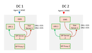
The following sample diagram illustrates the flow when one of the SIP phones registers:
- SIP phone 1 registers by sending a SIP REGISTER request to data center 1 (DC 1).
- SIP Server 1 becomes an owner of DN1.
- DN1 is set to in-service state (InSrv) on SIP Server 1.
- DN state is passed to the local routing Stat Server through the T-Controller port (TCport).
- DN state is passed to the remote SIP Server 2 through the T-Controller layer.
- SIP Server 2 distributes the DN state to the Stat Server 2 through the TCport.
DN State for PSTN Agents
DN ownership for PSTN agents is defined by the T-Library registration, TRegisterAddress request, sent from the Workspace Web Edition (WWE) application into which an agent logs in. The SIP Cluster node received the registration becomes the owner of that DN.
If WWE is not connected, Genesys Web Services (GWS) does not register agent DNs and the initial state of their DNs is out of service (OOS).
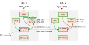
The following diagram illustrates the flow when WWE1 connects to GWS and an agent DN is registered:
- Agent 1 logs in to WWE and GWS registers on DN1.
- SIP Server 1 becomes an owner of DN1.
- SIP Server 1 distributes EventDNBackInService to the local Stat Server and to SIP Server 2.
- DN1 is set to in-service state (InSrv) on SIP Server 1 and SIP Server 2.
- DN state is passed to the local routing Stat Server through the T-Controller port (TCport).
- DN state is passed to the remote SIP Server 2 through the T-Controller layer.
- SIP Server 2 distributes the DN state to the Stat Server 2 through the TCport.
DN Availability for Routing
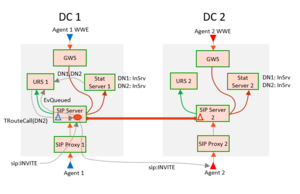
The following diagram illustrates how an inbound call is routed to an agent when the SIP Cluster nodes are connected and both DNs (DN1 and DN2) are registered. The call from data center 1 is routed to DN2 on data center 2. A call can be routed from any node to any agent.
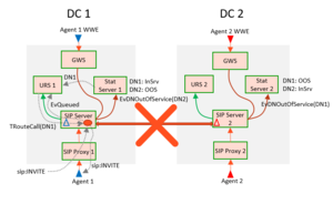
The following diagram illustrates the flow when the connection between two SIP Cluster nodes is lost:
As soon as the connection is lost, the DN owner is no longer connected and events for that particular DN cannot be received. SIP Server 1 places DN2 owned by SIP Server 2 into out of service, and vice versa, SIP Server 2 places DN1 owned by SIP Server 1 into out of service. Each SIP Cluster node continues routing to the locally owned DNs.
Next topic: Agent Reservation in SIP Cluster


