Universal_Routing
A Genesys CIM Platform component that provides voice-routing capabilities When it is combined with Multimedia, various types of non-voice media can also be routed. These two components work together to enable seamless routing of both voice and non-voice interactions. More information on Universal Routing is provided here.
Glossary
Interactive Voice Response
Also known as IVR. A hardware and software system that uses responses from a touch-tone telephone to gather and store data. It uses a recorded human voice to reply to user input. It is sometimes referred to as the Voice Response Unit (VRU).
IVR can also refer to systems that provide information in the form of recorded messages over telephone lines, in response to user-supplied input in the form of spoken words or, more commonly, Dual-Tone Multi Frequency (DTMF) signaling. Examples include banks that enable you to check your balance from any telephone, and automated stock-quote systems. For example, For checking account information, press 1 or If you want a stock quote, press 2.
A computer technology that enables users to connect to a computer system and obtain information through voice input, instead of by using a keypad, keyboard, or touch-tone telephone device. An IVR system responds to a human voice, looks up information, presents alternatives, and interacts with the caller.
Glossary
Contents
Universal Routing Assisted by IVR-Behind-Switch Call Flows
This page illustrates voice inbound call flows that use IVRs in a Genesys Universal Routing solution, where the IVR is deployed behind the switch.
Voice interactions that arrive at the switch are queued to an ACD queue, where the ACD positions are actually IVR DNs. The IVR collects digits and information about the caller and transfers the call to a Routing Point. Universal Routing uses the collected information to select an appropriate routing target. Basic targets are ACD queues and individual DNs. More advanced targets are agent groups, place groups, and skill expressions.
The following call flows are supported:
- Inbound call — Routing Point routes to ACD queue
- Inbound call — Routing Point routes to agent
- Inbound call to ACD and parallel IVR
Inbound call — Routing Point routes to ACD queue
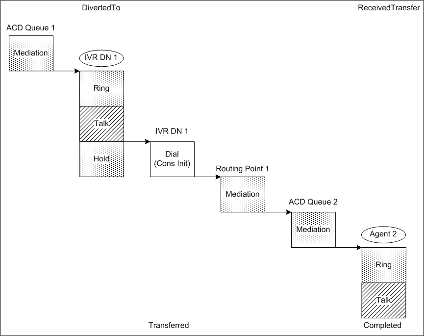
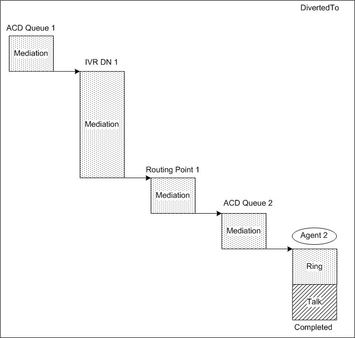
This call topology shows the outcome of a call that is routed to an agent via an ACD queue. The call arrives at an ACD queue and is diverted to an IVR DN. The IVR then transfers the call to a Routing Point, which routes the call to an ACD queue. The following diagrams illustrate the outcomes for:
Routing Point routes to ACD queue (self-service IVR)
| This diagram depicts the IRF representation of the call topology in the case of a self-service (SS) IVR (when the IVR is in its own box). Technical Descriptors illustrated:
|
Routing Point routes to ACD queue &mdash (nonself-service IVR)
| This diagram depicts the IRF representation of the call topology in the case of a nonself-service (nonSS) IVR.
Technical Descriptors illustrated:
|
Inbound call — Routing Point routes to agent
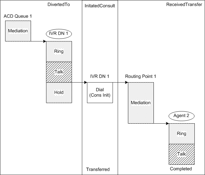
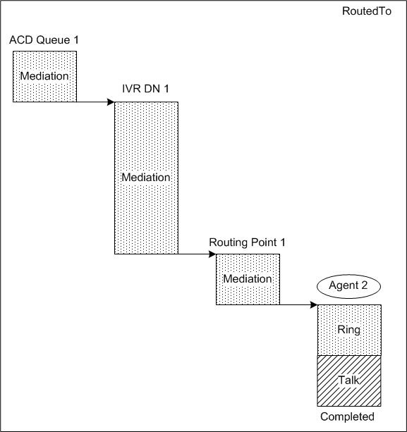
This call topology shows the outcome of a call that is routed directly to an agent. The call arrives at an ACD queue and is diverted to an IVR DN. The IVR then transfers the call to a Routing Point, which routes the call to an agent. The following diagrams illustrate the outcomes for:
Routing Point routes to agent (self-service IVR)
| This diagram depicts the IRF representation of the call topology in the case of an SS IVR (when the IVR is in its own box). Technical Descriptors illustrated:
|
Routing Point routes to agent (nonself-service IVR)
| This diagram depicts the IRF representation of the call topology in the case of a nonSS IVR.
Technical Descriptors illustrated:
|
Inbound call to ACD and parallel IVR
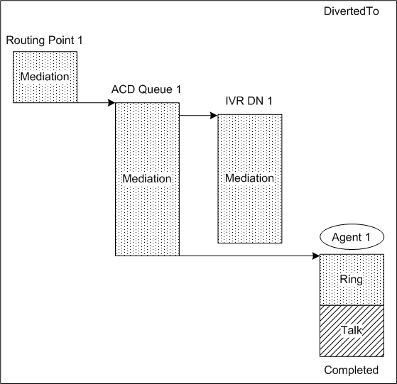
| This call topology shows the outcome of a call that arrives at a Routing Point, which diverts the call to an ACD queue. While the call is queued at the ACD, the ACD interacts with an IVR, which collects a transfer number from the customer. The IVR returns the collected digits to the ACD, after which the ACD diverts the call to the customer-entered number.This diagram depicts the IRF representation of the call topology in the case of a nonSS IVR.
Technical Descriptors illustrated:
|

