
Windows NLB Cluster
Complete these steps to set up SIP Server HA on Windows, using Windows Network Load Balancing (NLB) Cluster functionality.
Windows NLB Cluster HA Deployment
Prerequisites
The following are the basic requirements and recommendations that must be complete before you can deploy a SIP Server HA configuration in a Windows NLB Cluster environment.
- Two separate physical host computers: one for the primary SIP Server and one for the backup SIP Server.
Note: Genesys recommends that you install primary and backup instances of SIP Server on different host computers. However, SIP Server does support HA configurations in which both primary and backup SIP Server instances reside on a single host server.
- Operating-system requirement:
- Windows Server 2003 or Windows Server 2008 with Microsoft Windows Network Load Balancing (NLB).
- Software requirements:
- SIP Server must be installed and configured on both host computers.
- Local Control Agent (LCA) must be installed and configured on both host computers.
- Networking requirements:
- A name-resolution method such as Domain Name System (DNS), DNS dynamic-update protocol, or Windows Internet Name Service (WINS) is required.
- Both host computers must be members of the same domain.
- A domain-level account that is a member of the local Administrators group is required on each host computer. A dedicated account is recommended.
- Each host computer must have a unique NetBIOS name.
- A static IP address is required for each of the network interfaces on both host computers. Note: Server clustering does not support IP addresses that are assigned through Dynamic Host Configuration Protocol (DHCP) servers.
- A dedicated network switch or separate virtual local-area network (VLAN) for cluster adapters is recommended to reduce switch flooding that might be caused by Windows NLB.
- Access to a domain controller is required. If the cluster service is unable to authenticate the user account that is used to start the service, the cluster might fail. It is recommended that the domain controller be on the same local-area network (LAN) as the cluster, to ensure availability.
- Each node must have at least two network adapters: one for the connection to the public network and another for the connection to the private node-to-node cluster network.
- A dedicated private-network adapter is required for HCL certification.
- All nodes must have two physically independent LANs or VLANs for public and private communication.
- If you are using fault-tolerant network cards or network-adapter teaming, verify that firmware and drivers are up to date, and check with your network-adapter manufacturer for Windows NLB cluster compatibility.
- In deployments where SIP Server uses two NICs, one NIC is used for SIP communication, while the second NIC is used for other kinds of communication with various components. Each host has one NIC connected to a subnet dedicated to SIP communication. The Virtual IP address should be within the range of the network to which the NIC dedicated to SIP communication is connected. The second NIC on both hosts should be connected to a separate network.
Configuring Windows NLB cluster parameters
To configure Windows NLB cluster parameters that are required for this type of SIP Server HA deployment. Use the Microsoft Network Load Balancing (NLB) Manager to configure load-balancing parameters, as described in the following procedure.
- Open the Microsoft Network Load Balancing Manager tool.
- Select a cluster host, and open the Cluster Properties window.
- On the Cluster Parameters tab, select the Cluster operation mode. You can choose either Unicast (default) or Multicast mode. For information about Windows NLB Unicast and Multicast modes, refer to your Microsoft Windows Server documentation.
- Click the Port Rules tab.
- Specify a Port range that includes the port that you will assign as the sip-port. See "Configuring the primary SIP Server".
- In the Protocols section, select Both (both UDP and TCP).
- In the Filtering mode section, select Multiple host, and set Affinity to either None or Single.
- Set Load weight to Equal.
- Click the Host Parameters tab. In the Initial host state section, set the Default state to Stopped.
For more information about Windows NLB cluster parameters, refer to your Microsoft Windows Server documentation.
Configuring the primary SIP Server
Purpose
To configure the primary SIP Server Application object for high availability.
- Stop the SIP Server applications on the primary and backup hosts. Genesys SIP Server applications can be stopped by using the Genesys Solution Control Interface.
- Open the Configuration Manager.
- Select the Applications folder, and right-click the SIP Server Application object that you want to configure as the primary SIP Server. Select Properties.
- Click the Options tab.
- Select the TServer section.
- Set the sip-port option to the port number that will be used by both the primary and backup SIP Server applications.
- Set the sip-address option to the Virtual IP address. (For Windows NLB cluster configurations, set the value to the Windows NLB cluster IP address).
- Click Apply to save the configuration changes.
- If you are deploying a hot-standby configuration, it is recommended that you enable ADDP for communication between the primary and backup SIP Servers. To enable ADDP:
- Select the backup-sync section, and configure the following options:
- sync-reconnect-tout
- protocol
- addp-timeout
- addp-remote-timeout
 Configuring the backup-sync Options: Sample Configuration
In the preceding example, the guideline that is used to configure ADDP settings is to set the addp-timeout and addp-remote-timeout options to at least two times the established network-latency time, and to set the sync-reconnect-tout option to at least two times the timeout value plus the established network latency.
Note: For more information about ADDP configuration parameters, see the "Backup-Synchronization Section" section in the Framework 8.1 SIP Server Deployment Guide. - Select the backup-sync section, and configure the following options:
- Click Apply to save the configuration changes.
- Select the TServer section.
- Click the Switches tab.
- Ensure that the correct Switch object is specified. If necessary, select the correct Switch object by using the Add button.
- Click Apply to save the configuration changes.
- Click the Server Info tab.
- Select the Redundancy Type. You can select either Hot Standby or Warm Standby.
- Complete this step if you are deploying a hot-standby configuration. If you are deploying a warm-standby configuration, proceed to Step c.
- In the Ports section, select the port to which the backup SIP Server will connect for HA data synchronization, and click Edit Port.
- In the Port Properties dialog box, on the Port Info tab, select the HA sync check box.
- Click OK.
- For the Backup Server option, select the SIP Server Application object that you want to use as the backup SIP Server. If necessary, browse to locate the backup SIP Server Application object.
- Click Apply to save the configuration changes.
Note: If the HA sync check box is not selected, the backup SIP Server will connect to the default port of the primary SIP Server.
- Click the Start Info tab.
- Select Auto-Restart.
- Click Apply to save the configuration changes.
- Click Apply and then OK to save the configuration changes.

Configuring the backup SIP Server
To configure the backup SIP Server Application object for high availability.
- Stop the SIP Server applications on the primary and backup hosts. Genesys SIP Server applications can be stopped by using the Genesys Solution Control Interface.
- Open the Configuration Manager.
- Select the Applications folder, and right-click the SIP Server Application object that you want to configure as the backup SIP Server. Select Properties.
- Click the Switches tab.
- Click Add, and select the Switch object that you associated with the primary SIP Server Application object.
- Click Apply to save the configuration changes.
- Click the Start Info tab.
- Select Auto-Restart.
- Click Apply to save the configuration changes.
- Click the Options tab.
- Select the TServer section.
- Set the sip-port option to the same port number that you specified for the primary SIP Server.
- Set the sip-address option to the Virtual IP address. (For Windows NLB cluster configurations, set the value to the Windows NLB cluster IP address)
- Click Apply to save the configuration changes.
- If you are deploying a hot-standby configuration and have configured ADDP communication on the primary SIP Server, you must configure ADDP also on the backup SIP Server. To enable ADDP:
- Select the backup-sync section, and configure the following options:
- sync-reconnect-tout
- protocol
- addp-timeout
- addp-remote-timeout
In the preceding example, the guideline that is used to configure ADDP settings is to set the addp-timeout and addp-remote-timeout options to at least two times the established network-latency time, and to set the sync-reconnect-tout option to at least two times the timeout value plus the established network latency. Configuring the backup-sync Options: Sample Configuration - Select the backup-sync section, and configure the following options:
- Click Apply to save the configuration changes.
- Select the TServer section.
- Click Apply and then OK to save the configuration changes.
Creating Cluster control scripts
To create Cluster control scripts for each of the SIP Servers. The scripts are used to enable the Virtual IP port on the host on which the SIP Server is in primary mode and disable the Virtual IP port on the host on which the SIP Server is in backup mode.
In this procedure, you will create the following four Cluster control scripts:
- sip_server_primary_vip_up.bat—Enables the Virtual IP port on the primary SIP Server host
- sip_server_primary_vip_down.bat—Disables the Virtual IP port on the primary SIP Server host
- sip_server_backup_vip_up.bat—Enables the Virtual IP port on the backup SIP Server host
- sip_server_backup_vip_down.bat—Disables the Virtual IP port on the backup SIP Server host
Note: You can use the previously listed script names, or you can specify your own.
- On the primary SIP Server host computer, create a batch file that is named sip_server_primary_vip_up.bat and enter the following commands:
[+] Commands for sip_server_primary_vip_up.bat - On the primary SIP Server host computer, create a batch file that is named sip_server_primary_vip_down.bat and enter the following commands:
[+] Commands for sip_server_primary_vip_down.bat - On the backup SIP Server host computer, create a batch file that is named sip_server_backup_vip_up.bat and enter the following commands:
[+] Commands for sip_server_backup_vip_up.bat - On the backup SIP Server host computer, create a batch file that is named sip_server_backup_vip_down.bat and enter the following commands:
[+] Commands for sip_server_backup_vip_down.bat
Note: The preceding scripts include commands for logging script execution. The logs are created in the directory in which the script is located.
Creating Application objects for Cluster control scripts
To create four Application objects of type Third Party Server: one for each of the Cluster control scripts that you created in Step 5. For example:
- SIP_SERVER_PRIMARY_VIP_UP—For a script that enables the Virtual IP port on the primary SIP Server host
- SIP_SERVER_PRIMARY_VIP_DOWN—For a script that disables the Virtual IP port on the primary SIP Server host
- SIP_SERVER_BACKUP_VIP_UP—For a script that enables the Virtual IP port on the backup SIP Server host
- SIP_SERVER_BACKUP_VIP_DOWN—For a script that disables the Virtual IP port on the backup SIP Server host
Creating Application objects for the Cluster control scripts allows the scripts to be run as applications within the Genesys Framework.
- In the Configuration Manager, select Environment > Applications.
- Right-click and select New > Application.
- Select the Third Party Server template from the Application Templates folder, and click OK.
- On the General tab, enter the name for the Application object—for example, SIP_SERVER_PRIMARY_VIP_UP.
 Configuring the Application Object for the Script, General Tab: Sample Configuration
Note: You can use the suggested Application object names, or you can specify your own.
- Select the Server Info tab.
- Select the host name of the SIP Server on which the corresponding Cluster control script is located.
- If necessary, specify a valid communication-port number by using the Edit Port option.
 Configuring the Application Object for the Script, Server Info Tab: Sample Configuration
 - Select the Start Info tab.
- Set the Working Directory to the location of the control script, and enter the name of the script in the Command Line field. For example, for the SIP_SERVER_PRIMARY_VIP_UP Application object, enter the script name that enables the Virtual IP port (sip_server_primary_up.bat). For the SIP_SERVER_PRIMARY_VIP_DOWN Application object, enter the script name that disables the Virtual IP port (sip_server_primary_down.bat).
 Configuring the Application Object for the Script, Start Info Tab: Sample Configuration
 - If you are configuring an Application object that disables a Virtual IP port (SIP_SERVER_PRIMARY_VIP_DOWN and SIP_SERVER_BACKUP_VIP_DOWN), set the Timeout Startup value to 8.
- Repeat the steps in this procedure to create an Application object for each of the four Cluster control scripts.


Creating Alarm Reaction scripts
To create Alarm Reaction scripts for HA-related Alarm Conditions. When an HA-related Alarm Condition occurs, the associated Alarm Reaction script is run. Alarm Reaction scripts are configured to call the Application objects that you created in Step 6.
- Open the Configuration Manager.
- Select Resources > Scripts.
- Right-click and select New > Script.
- Create four scripts: one for each of the Application objects that you created previously. For example:
- AR_SCRIPT_PRIMARY_VIP_UP—To trigger a script that enables the Virtual IP address (to be run on the primary SIP Server host)
- AR_SCRIPT_PRIMARY_VIP_DOWN—To trigger a script that disables the Virtual IP address (to be run on the primary SIP Server host)
- AR_SCRIPT_BACKUP_VIP_UP—To trigger a script that enables the Virtual IP address (to be run on the backup SIP Server host)
- AR_SCRIPT_BACKUP_VIP_DOWN—To trigger a script that disables the Virtual IP address (to be run on the backup SIP Server host)
 Configuring the Alarm Reaction Script: Sample Configuration
 - For each of the Alarm Reaction scripts, select Alarm Reaction as the Script Type.
- For each of the Alarm Reaction scripts, use the Alarm Reaction Wizard to configure the Alarm Reaction Type.
- Select an Alarm Reaction script, and right-click to open the Alarm Reaction Wizard (select Wizard > Configure).
- In the Alarm Reaction Wizard, click Next.
- In the Alarm Reaction Type dialog box, select Start a specified application, and click Next.
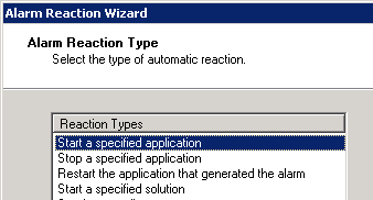 Alarm Reaction: Selecting the Alarm Reaction Type
 - Browse to select the corresponding Application object. For example, for the AR_SCRIPT_PRIMARY_VIP_UP Alarm Reaction script, select the SIP_SERVER_PRIMARY_VIP_UP Application object of type Third Party Server.
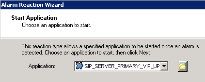 Alarm Reaction: Selecting the Application to Start
 - Repeat the previous steps to configure each of the Alarm Reaction scripts that you created in Step 4.


Creating Alarm Conditions
Alarm Conditions are required to handle log events that occur when a SIP Server changes its mode from primary to backup or from backup to primary. When you create the Alarm Conditions, you will configure them to trigger the Alarm Reaction scripts that you created in Step 7.
Four Alarm Conditions are required for your HA configuration: two for the primary SIP Server application and two for the backup. The following table outlines the Alarm Conditions for both hot-standby and warm-standby configurations.
| Log Event ID | SIP Server Application | Alarm Condition | Alarm Reaction Scripts
|
|---|---|---|---|
| 00-05151 | SIP_SERVER_PRIMARY | ALRM_PRIMARY_51_HABackup | AR_SCRIPT_PRIMARY_VIP_DOWN |
| 00-05150 | SIP_SERVER_PRIMARY | ALRM_PRIMARY_50_HAPrimary | AR_SCRIPT_BACKUP_VIP_DOWN AR_SCRIPT_PRIMARY_VIP_UP |
| 00-05151 | SIP_SERVER_BACKUP | ALRM_BACKUP_51_HABackup | AR_SCRIPT_BACKUP_VIP_DOWN |
| 00-05150 | SIP_SERVER_BACKUP | ALRM_BACKUP_50_HAPrimary | AR_SCRIPT_BACKUP_VIP_UP AR_SCRIPT_PRIMARY_VIP_DOWN |
For information about the log events for which you are creating Alarm Conditions, refer to Log events generated by SCS.
- Open the Configuration Manager.
- Navigate to the Environment > Alarm Conditions folder.
- Right-click and select New > Alarm Condition to open the New Alarm Condition Properties dialog box.
- On the General tab:
- Enter the Name for the Alarm Condition—for example, ALRM_PRIMARY_51_HABackup.
- Optionally, enter a description.
- For the Category value, select Critical.
- Set Cancel Timeout to 1.
 Configuring the Alarm Condition, General Tab: Sample Configuration
 - On the Detect Event tab:
- Set the Log Event ID as defined in the table above.
- Set the Selection Mode to Select By Application.
- For the Application Name field, click the folder icon to browse for the SIP Server Application object. If you are creating an Alarm Condition for the primary SIP Server, select the primary SIP Server Application object. If you are creating an Alarm Condition for the backup SIP Server, select the backup SIP Server Application object.
 Configuring the Alarm Condition, Detect Event Tab: Sample Configuration
 - Click OK.
- On the Reaction Scripts tab, add the Alarm Reaction script as defined in the previous table.
- Repeat the steps in this procedure to create each of the four Alarm Conditions for your configuration.


Testing Alarm Conditions
To verify that the Alarm Conditions work as expected.
- Open the Solution Control Interface (SCI).
- Under Alarm Conditions, select the Alarm Condition that you created in the previous procedure—for example, ALRM_PRIMARY_51_HABackup—right-click it, and then click Test. The ALRM_PRIMARY_51_HABackup Alarm Condition indicates that the primary SIP Server is in backup mode, which triggers the Alarm Reaction scripts that disable the Virtual IP portat the primary SIP Server and disable the Virtual IP port at the backup SIP Server.
- Use an wlbs queryport command to verify that the Virtual IP port is disabled on the primary SIP Server and that the Virtual IP port is enabled on the backup SIP Server.
Testing your SIP Server HA configuration
To validate your HA configuration, you can perform the following tests.
- Ensure that the Management Layer is up and running.
- Start the primary SIP Server, and ensure that it is in primary mode.
- Start the backup SIP Server, and ensure that it is in backup mode.
- Test 1: Manual switchover
- Establish a call between two SIP endpoints.
- Perform a manual switchover by using the SCI. In the SCI, verify that the SIP Server roles have changed.
- Verify that hold, retrieve, and transfer functions can be performed on the call that was established before the switchover.
- Release the call.
- Test 2: Manual switchback
- Establish a call between two SIP endpoints.
- Perform a manual switchover again by using the SCI. In the SCI, verify that the SIP Server roles have changed.
- Verify that hold, retrieve, and transfer functions can be performed on the call that was established before the switchover.
- Release the call.
- Test 3: Stop primary SIP Server
- Establish a call between two SIP endpoints.
- Stop the primary SIP Server. Use the SCI to verify that the backup SIP Server goes into primary mode.
- Verify that hold, retrieve, and transfer functions can be performed on the call that was established before the switchover.
- Release the call.